February 1, 2017

Generating Electricity from a Bicycle Dynamo

The proposed mini-electricity generator project is very simple to build and can be used by students as a school project, or just for hobbyists. The set up can be used to charge a battery with electricity produced from wind power.A dynamo is a type of alternator commonly associated with bicycles for generating electricity that is used for lighting a small head lamp. The unit eliminates the need of a battery and provides an easy alternative for illuminating a lamp whenever the bicycle is in motion.

A dynamo is a type of alternator commonly associated with bicycles for generating electricity that is used for lighting a small head lamp. The unit eliminates the need of a battery and provides an easy alternative for illuminating a lamp whenever the bicycle is in motion.

A dynamo is a pretty interesting little generator which starts generating pure electricity the moment its wheel is rotated. Basically, it works on the fundamental principles of electromagnetism where current is induced in coils of copper wire under the influence of a rotating magnetic flux, generated by alternate shifting of the magnets North and south poles.

Before we move on to the actual project, interested enthusiasts may try building a homemade dynamo with the help of the explanation provided in the following section.

How to Make a Homemade Dynamo

You will need the following materials:
  • A flat iron bar = six inches long, half mm in thickness,
  • Super enamelled copper wire = 28 to 30 SWG, 25 meters approximately,
  • Small magnet bar = square in shape, 1.5 square inch, half mm in thickness.
  • Suitable spindle, clamp, wheel mechanism set-up as discussed in the text and in the diagram.
  • Torch Bulb = 3 Volts
Procedure:

Bend the iron bar in “U” shape with dimensions as shown in the diagram.
Cover the horizontal portion of the “U” with a reasonably thick paper former or insulate it with some kind of PVC tape.
 
Wind the copper wire neatly and gently over the above-dressed section of the “U” channel, through uniform overlapping steps, until you have at least 6 inches of wire ends left for external connections.
 
Take the magnet and fix it (by glueing or some other suitable method) over a central metal rod and arrange the mechanism just as directed in the diagram.
 
Connect the coil ends to a small 3-volt torch bulb.
Now it’s just a matter of rotating the central rod/magnet assembly as fast as the mechanism permits.
 
If the winding and the mechanism specifications are perfectly optimised, it will instantly produce a nice glow over the filament of the bulb.
 
Your homemade DIY dynamo is ready.
 
However, the above make cannot be even close to a readymade dynamo as far as efficiency is concerned, so for our next main project, we would want to procure a good quality readymade bicycle dynamo.

Iron Carbon Phase Diagram

The iron carbon phase diagram shown in Fig 1 actually shows two diagrams i) the stable iron-graphite diagram (dashed lines) and the metastable Fe-Fe3C diagram. The stable condition usually takes a very long time to develop specially in the low temperature and low carbon range hence the metastable diagram is of more interest.

iron carbon phase diagram
Many of the basic features of this irpn carbon system also influence the behavior of alloy steels. For example, the phases available in the simple binary Fe-C system are also available in the alloy steels, but it is essential to examine the effects of the alloying elements on the formation and properties of these phases. The iron-carbon diagram provides a solid base on which to build the knowledge of both plain carbon and alloy steels.

There are some important metallurgical phases and micro constituents in thr iron carbon system. At the low-carbon end is the ferrite (?-iron) and austenite (?-iron). Ferrite can at most dissolve 0.028 wt% C at 727 deg C and austenite (?-iron) can dissolve 2.11 wt% C at 1148 deg C. At the carbon-rich side there is cementite (Fe3C).

iron carbon phase diagram
Between the single-phase fields are found regions with mixtures of two phases, such as ferrite & cementite, austenite & cementite, and ferrite & austenite. At the highest temperatures, the liquid phase field can be found and below this are the two phase fields liquid & austenite, liquid & cementite, and liquid & ferrite. In heat treating of steels, the liquid phase is always avoided. Some important boundaries at single-phase fields have been given special names that facilitate the understanding of the diagram.


Main micro-structures of iron and steels in equilibrium are
 
1. Austenite or ?-iron phase – Austenite is a high temperature phase and has a Face Centred Cubic (FCC) structure (which is a close packed structure). ?-iron is having good strength and toughness but it is unstable below 723 deg C.

2. Ferrite or ?-iron phase – It is relatively soft low temperature phase and is a stable equilibrium phase. Ferrite is a common constituent in steels and has a Body Centred Cubic (BCC) structure (which is less densely packed than FCC). ?-iron is soft , ductile and has low strength and good toughness.

3. Cementite – It is Fe3C or iron carbide. It is intermediate compound of Fe and C. It has a complex orthorhombic structure and is a metastable phase. It is hard, brittle and has low tensile strength, good compression strength and low toughness

4. Pearlite is the ferrite-cementite phase mixture. It has a characteristic appearance and can be treated as a micro structural entity or micro constituent. It is an aggregate of alternating ferrite and cementite lamellae that degenerates (“spheroidizes” or “coarsens”) into cementite particles dispersed with a ferrite matrix after extended holding below 723 deg C. It is a eutectoid and has BCC structure. It is a partially soluble solution of Fe and C. It has high strength and low toughness.

Bourdon Tube Pressure Gauge Diagram


Packaged Air Conditioners – Types of Packaged AC

This article describes what the package air conditioner is and the types of packaged air conditioners.
The window and split air conditioners are usually used for the small air conditioning capacities up to 5 tons. The central air conditioning systems are used for where the cooling loads extend beyond 20 tons. The packaged air conditioners are used for the cooling capacities in between these two extremes. The packaged air conditioners are available in the fixed rated capacities of 3, 5, 7, 10 and 15 tons. These units are used commonly in places like restaurants, telephone exchanges, homes, small halls, etc.

As the name implies, in the packaged air conditioners all the important components of the air conditioners are enclosed in a single casing like window AC. Thus the compressor, cooling coil, air handling unit and the air filter are all housed in a single casing and assembled at the factory location.

Depending on the type of the cooling system used in these systems, the packaged air conditioners are divided into two types: ones with water cooled condenser and the ones with air cooled condensers. Both these systems have been described below:

Packaged Air Conditioners with Water Cooled Condenser

In these packaged air conditions the condenser is cooled by the water. The condenser is of shell and tube type, with refrigerant flowing along the tube side and the cooling water flowing along the shell side. The water has to be supplied continuously in these systems to maintain functioning of the air conditioning system.
The shell and tube type of condenser is compact in shape and it is enclosed in a single casing along with the compressor, expansion valve, and the air handling unit including the cooling coil or the evaporator. This whole packaged air conditioning unit externally looks like a box with the control panel located externally.

packaged units with the water cooled condenser, the compressor is located at the bottom along with the condenser (refer the figure below). Above these components the evaporator or the cooling coil is located. The air handling unit comprising of the centrifugal blower and the air filter is located above the cooling coil. The centrifugal blower has the capacity to handle large volume of air required for cooling a number of rooms. From the top of the package air conditioners the duct comes out that extends to the various rooms that are to be cooled.

All the components of this package AC are assembled at the factory site. The gas charging is also done at the factory thus one does not have to perform the complicated operations of the laying the piping, evacuation, gas charging, and leak testing at the site. The unit can be transported very easily to the site and is installed easily on the plane surface. Since all the components are assembled at the factory, the high quality of the packaged unit is ensured.

Package AC with Water Cooled Condenser
Packaged Air Conditioners with Air Cooled Condensers

In this packaged air conditioners the condenser of the refrigeration system is cooled by the atmospheric air. There is an outdoor unit that comprises of the important components like the compressor, condenser and in some cases the expansion valve (refer the figure below). The outdoor unit can be kept on the terrace or any other open place where the free flow of the atmospheric air is available. The fan located inside this unit sucks the outside air and blows it over the condenser coil cooling it in the process. The condenser coil is made up of several turns of the copper tubing and it is finned externally. The packaged ACs with the air cooled condensers are used more commonly than the ones with water cooled condensers since air is freely available it is difficult maintain continuous flow of the water.

The cooling unit comprising of the expansion valve, evaporator, the air handling blower and the filter are located on the floor or hanged to the ceiling. The ducts coming from the cooling unit are connected to the various rooms that are to be cooled.

Internal Combustion Engines: Introduction and Classification

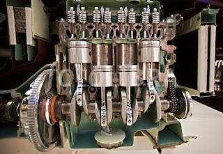
The inner burning motors are actually the motors where the burning from a gas accompanies an oxidizer (normally air) in a burning enclosure that is actually an important aspect of the operating liquid circulation circuit. In an interior burning motor, the development from the heat and also high-pressure fuels made through ignition administer straight pressure to some element from the motor. The force is actually administered normally to engines, generator cutters or even a faucet.

In an interior burning motor the development from the heat as well as high-pressure fuels made through burning use straight pressure to some element from the motor. The force is actually administered usually to engines, wind turbine cutters or even a mist nozzle.

Principal of Operation:


Air-fuel blend in the ignition enclosure is actually sparked, either through a fuse (in the event from SI Engines) or even through squeezing (just in case from CI motors). This ignition generates incredible volume from heat and also stress inside the cylindrical tube. This causes returning the compliment movement in the engine.
Energy from the engine is actually sent to a crankshaft which goes through turning activity. The rotating activity is actually essentially broadcast to the steering wheels of the car, by means of a gear box device, to make power in the motor vehicle.
As the ignition happens internally inside the cylindrical tube (an aspect of functioning liquid circuit) the motor is actually contacted inner burning motor.

Classification of Internal Combustion Engine:
 
1. Based on application
  • Automobile Engine
  • Aircraft Engine
  • Locomotive Engine
  • Marine Engine
  • Stationary Engine
2. Based on basic engine design
  • Reciprocating: Single cylinder, Multi-cylinder In-line, V, radial, opposed cylinder, Opposed Piston.
  • Rotatory: Single motor, Multi motor
3. Based on operating cycle
  • Atkinson (For complete expansion SI Engine)
  • Diesel (For the Ideal Diesel Engine)
  • Dual (For the Actual Diesel Engine)
  • Miller (For Early/Late Inlet valve closing type SI Engine)
  • Otto (For the Convectional SI Engine)
4. Based on working cycle
  • Four stroke cycle
  • Two stroke cycle
  • Scavenging ; direct/crankcase/cross flow; back flow/loop; Uni flow
  • Naturally aspirated or turbocharged
5. Based on Valve/port design and location
  • Design of valve/port
  • Poppet valve
  • Rotatory valve
  • Location of valve/port
  • T-head
  • L-head
  • F-head
  • L-head
6.Based on Fuel
  • Convectional
  • Crude oil derivatives; Petrol, diesel
  • Other sources; coal, bio-mass, tar stands, shale
  • Alternative
  • Petroleum derived: CNG, LPG
  • Bio-mass derived: alcohols, vegetable oils, producer gas, biogas and hydrogen
  • Blending
  • Bi-fuel and dual fuel
7. Based on mixture preparation
  • Carburetion
  • Fuel injection
8. Based on ignition
  • Spark ignition
  • Compression Ignition
9. Based on stratification of charge
  • Homogeneous Charge
  • Stratified charge
  • With carburetion
  • With fuel injection
10. Based on combustion chamber design
  • Open chamber: Disc, wedge, hemispherical, bowl-in-piston, bath tub.
  • Divided chamber:
    • (For CI) 1. Swirl chamber, 2. Pre-chamber
    • (for SI) 1. CVCC, 2. Other designs
11. Based on cooling system
  • Air-cooling system
  • Water-cooling system